13.1.10 Packet Tracer – Configure a Wireless Network (Instructor Version)
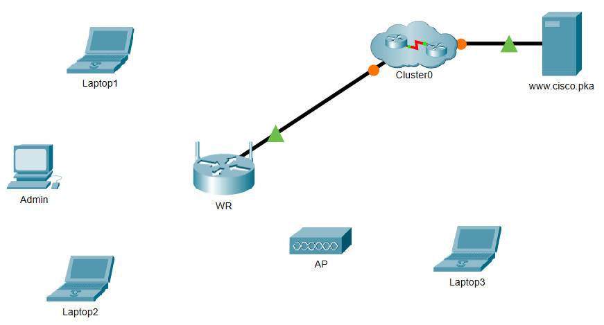
Objectives
- Connect to a wireless router
- Configure the wireless router
- Connect a wired device to the wireless router
- Connect a wireless device to the wireless router
- Add an AP to the network to extend wireless coverage
- Update default router settings
Introduction
In this activity, you will configure a wireless router and an access point to accept wireless clients and route IP packets. Furthermore, you will also update some of the default settings.
Instructions
Part 1: Connect to a Wireless Router
Step 1: Connect Admin to WR.
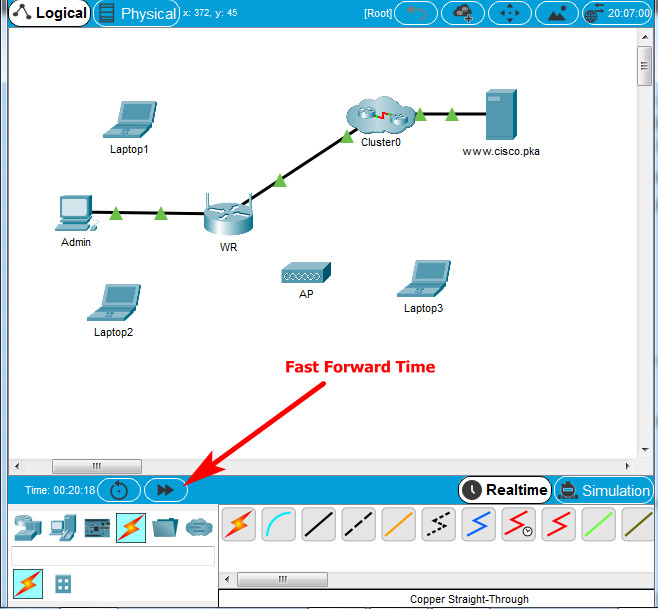
a. Connect Admin to WR using a straight-through Ethernet cable through the Ethernet ports. Select Connections, represented by a lightning bolt, from the bottom-left side of Packet Tracer. Click Copper Straight-Through, represented by a solid black line.
b. When the cursor changes to connection mode, click Admin and choose FastEthernet0. Click WR and choose an available Ethernet port to connect the other end of the cable.
WR will act as a switch to the devices connected to the LAN and as a router to the internet. Admin is now connected to the LAN (GigabitEthernet 1). When Packet Tracer displays green triangles on both sides of the connection between Admin and WR, continue to the next step.
Note: If no green triangles are shown, make sure to enable Show Link Lights under Options > Preferences. You may also click Fast Forward Time just above the Connections selection box in the yellow bar.
Step 2: Configure Admin to use DHCP.
To reach the WR management page, Admin must communicate on the network. A wireless router usually includes a DHCP server, and the DHCP server is usually enabled by default on the LAN. Admin will receive IP address information from the DHCP server on WR.
a. Click Admin, and select the Desktop tab.
b. Click IP Configuration and select DHCP.
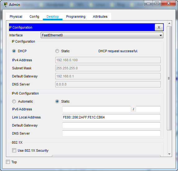
What is the IP address of the computer?
What is the subnet mask of the computer?
What is the default gateway of the computer?
c. Close the IP Configuration window.
Note: Values can vary within the network range due to normal DHCP operation.
Step 3: Connect to the WR Web Interface.
a. In the Desktop tab on Admin, choose Web Browser.
b. Enter 192.168.0.1 in the URL field to open the web configuration page of the wireless router.
c. Use admin for both the username and password.
d. Under the Network Setup heading on the Basic Setup page, notice the IP address range for the DHCP server.
Is the IP address for Admin within this range? Is it expected? Explain your answer.
Step 4: Configure the Internet Port of WR.
In this step, WR is configured to route the packets from the wireless clients to internet. You will configure the Internet port on WR to connect to the internet.
a. Under the Internet Setup at the top of the Basic Setup page, change the Internet IP address method from Automatic Configuration – DHCP to Static IP.
b. Type the IP address to be assigned to the Internet interface as follows:
Internet IP Address: 209.165.200.225
Subnet Mask: 255.255.255.252
Default Gateway: 209.165.200.226
DNS Server: 209.165.201.1
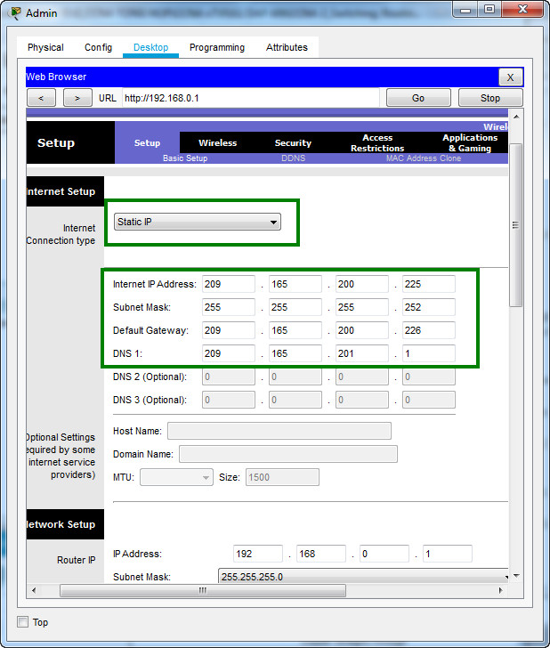
c. Scroll down the page and click Save Settings.
Note: If you get a Request Timeout message, close the Admin window and wait for the orange lights to turn into green triangles. Click the fast forward button to make this happen faster. Then reconnect to WR from Admin’s browser using the process explained in Step 3.
d. To verify connectivity, open a new web browser and navigate to www.cisco.pka server.
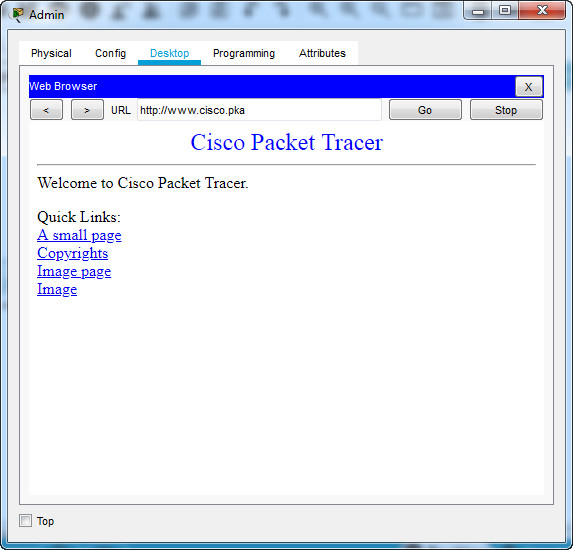
Note It may take a few seconds for the network to converge. Click Fast Forward Time or Alt+D to speed up the process.
Part 2: Configure the Wireless Settings
In this activity, you will only configure the wireless settings for 2.4 GHz.
Step 1: Configure the WR SSID.
a. Navigate to the WR GUI interface at 192.168.0.1 in a web browser on Admin.
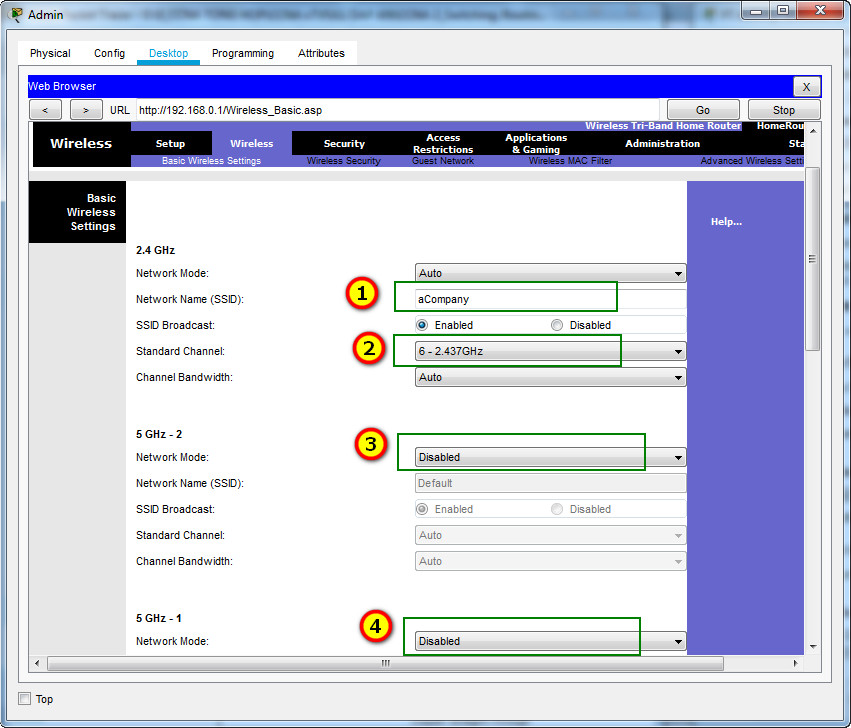
b. Navigate to Wireless > Basic Wireless Settings.
c. Change Network Name (SSID) to aCompany for only 2.4 GHz. Notice that SSIDs are case-sensitive.
d. Change the Standard Channel to 6 – 2.437GHz.
e. For this activity, disable both 5 GHz frequencies. Leave the rest of the settings unchanged.
f. Scroll to the bottom of the window and click Save Settings.
Step 2: Configure wireless security settings.
In this step, you configure the wireless security settings using WPA2 security mode with encryption and passphrase.
a. Navigate to Wireless > Wireless Security.
b. Under the 2.4 GHz heading, select WPA2 Personal for the Security Mode.
c. For the Encryption field, keep the default AES setting.
d. In the Passphrase field, enter Cisco123! as the passphrase.
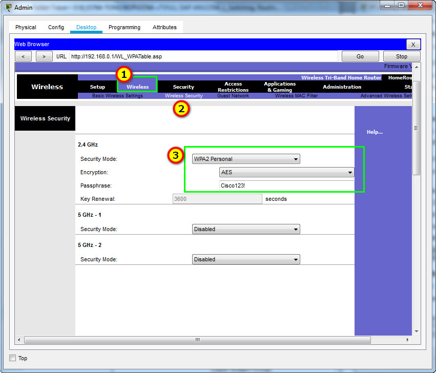
e. Click Save Settings.
f. Verify that the settings in the Basic Wireless Settings and Wireless Security pages are correct and saved.
Step 3: Connect the Wireless Clients.
a. Open Laptop1. Select Desktop tab. Click PC Wireless.
b. Select the Connect tab. Click Refresh as necessary. Select the Wireless Network Name aCompany.
c. Enter the passphrase configured in the previous step. Enter Cisco123! In the pre-shared key field and click Connect. Close the PC Wireless window.
d. Open a web browser and verify that you can navigate to www.cisco.pka server.
e. Repeat the above steps to connect Laptop2 to the wireless network.
Part 3: Connect Wireless Clients to an Access Point
An access point (AP) is a device that extends the wireless local area network. An access point is connected to a wired router using an Ethernet cable to project the signal to a desired location.
Step 1: Configure the Access Point.
a. Connect Port 0 of AP to an available Ethernet port of WR using a straight-through Ethernet cable.
b. Click AP. Select the Config tab.
c. Under the INTERFACE heading, select Port 1.
d. In the SSID field, enter aCompany.
e. Select WPA2-PSK. Enter the passphrase Cisco123! In the Pass Phrase field.
f. Keep AES as the default Encryption Type.
Step 2: Connect the Wireless Clients.
a. Open Laptop3. Select Desktop tab. Click PC Wireless.
b. Select the Connect tab. Click Refresh as necessary. Select the Wireless Network Name aCompany with the stronger signal (Channel 1) and click Connect.
c. Open a web browser and verify that you can navigate to www.cisco.pka server.
Part 4: Other Administrative Tasks
Step 1: Change the WR Access Password.
a. On Admin, navigate to WR GUI interface at 192.168.0.1.
b. Navigate to Administration > Management and change the current Router Password to cisco.
c. Scroll to the bottom of the window and click Save Settings.
d. Use the username admin and the new password cisco when prompted to log in to the wireless router.
Click OK to continue.
e. Click Continue and move on to the next step.
Step 2: Change the DHCP address range in WR.
In this step, you will change the internal network address from 192.168.0.0/24 to 192.168.50.0/24. When the LAN network address changes, the IP addresses on the devices in the LAN and WLAN must be renewed to receive new IP addresses before the lease is timed out.
a. Navigate to Setup > Basic Setup.
b. Scroll down the page to Network Setup.
c. The IP address assigned to Router IP is 192.168.0.1. Change it to 192.168.50.1. Verify that IP address still start at .100, and there are 50 available IP addresses in the DHCP pool.
d. Add 209.165.201.1 as the DNS server with the DHCP settings.
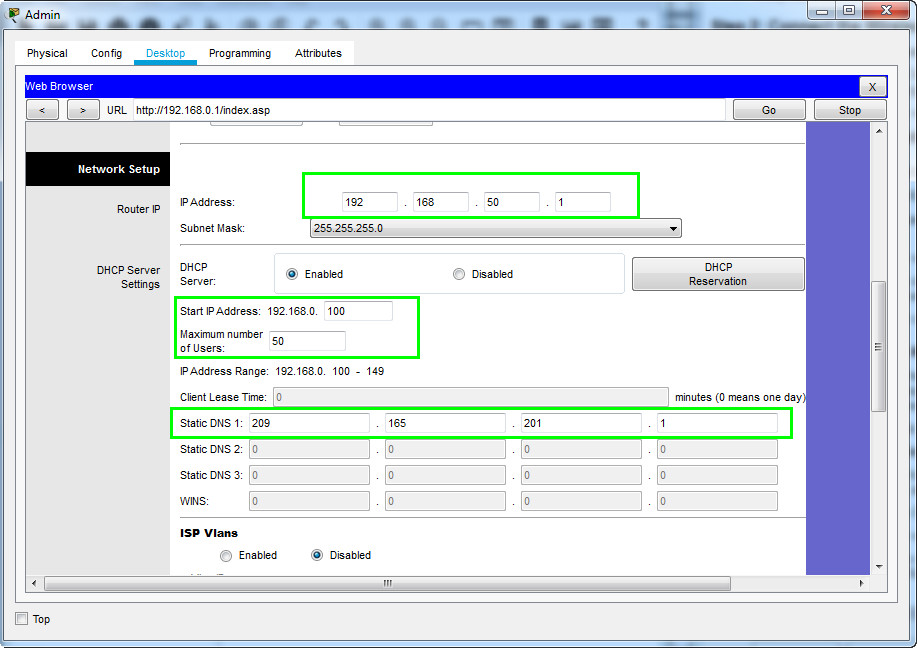
e. Scroll to the bottom of the window and click Save Settings.
f. Note that the DHCP range of addresses has been automatically updated to reflect the interface IP address change. The Web Browser will display a Request Timeout after a short time.
Why?
g. Close the Admin web browser.
h. In Admin Desktop tab, click Command Prompt.
i. Type ipconfig /renew to force Admin re-acquire its IP information via DHCP.
What is the new IP address information for Admin?
IP Address: …………………………. 192.168.50.100
Subnet Mask: ………………………….. 255.255.255.0
Default Gateway: ……………………… 192.168.50.1
DNS Server: ………………………………. 209.165.201.1
j. Verify that you can still navigate to www.cisco.pka server.
k. Renew the IP address on other laptops to verify that you can still navigate to www.cisco.pka server.
l. Notice that Laptop1 connected to the AP instead of WR.
Why?
Download PDF & PKA file Completed:
[sociallocker id=”54558″]
[wpdm_package id=’39165′]
[wpdm_package id=’39166′]
[/sociallocker]
[alert-note][one_half]
Previous Lab
11.6.1 Packet Tracer – Switch Security Configuration
[/one_half][one_half_last]
Next Lab
13.2.7 Packet Tracer – Configure a Basic WLAN on the WLC
[/one_half_last][/alert-note]

scripts pls
script my cock
You dont need scrpits for this assigment.
I would like to just say thank you for all the help with the answers and explaining the problems.