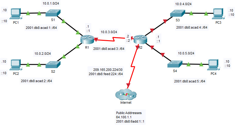
14.3.5 Packet Tracer – Basic Router Configuration Review (Instructor Version)

Addressing Table
| Device | Interface | IP Address / Prefix | Default Gateway |
|---|---|---|---|
| R2 | G0/0/0 | 10.0.4.1 /24 | N/A |
| 2001:db8:acad:4::1 /64 | |||
| fe80::2:a | |||
| G0/0/1 | 10.0.5.1 /24 | ||
| 2001:db8:acad:5::1 /64 | |||
| fe80::2:b | |||
| S0/1/0 | 10.0.3.2 /24 | ||
| 2001:db8:acad:3::2 /64 | |||
| fe80::1:c | |||
| S0/1/1 | 209.165.200.225 /30 | ||
| 2001:db8:feed:224::1/64 | |||
| fe80::1:d | |||
| PC1 | NIC | 10.0.1.10 /24 | 10.0.1.1 |
| 2001:db8:acad:1::10 /64 | fe80::1:a | ||
| PC2 | NIC | 10.0.2.10 /24 | 10.0.2.1 |
| 2001:db8:acad:2::10 /64 | fe80::1:b | ||
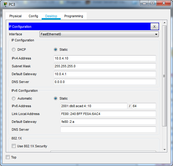
| PC3 | NIC | 10.0.4.10 /24 | 10.0.4.1 |
| 2001:db8:acad:4::10 /64 | fe80::2:a | ||
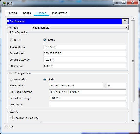
| PC4 | NIC | 10.0.5.10 /24 | 10.0.5.1 |
| 2001:db8:acad:5::10 /64 | fe80::2:b |
Objectives
Part 1: Configure Devices and Verify Connectivity
- Assign static IPv4 and IPv6 addresses to the PC interfaces.
- Configure basic router settings.
- Configure the router for SSH.
- Verify network connectivity.
Part 2: Display Router Information
- Retrieve hardware and software information from the router.
- Interpret the startup configuration.
- Interpret the routing table.
- Verify the status of the interfaces.
Background / Scenario
This activity requires you to configure the R2 router using the settings from the Addressing Table and the specifications listed. The R1 router and the devices connected to it have been configured. This is a comprehensive review of previously covered IOS router commands. In Part 1, you will complete basic configurations and interface settings on the router. In Part 2, you will use SSH to connect to the router remotely and utilize the IOS commands to retrieve information from the device to answer questions about the router. For review purposes, this lab provides the commands necessary for specific router configurations.
Instructions
Part 1: Configure Devices and Verify Connectivity
Step 1: Configure the PC interfaces.
a. Configure the IPv4 and IPv6 addresses on PC3 as listed in the Addressing Table.
b. Configure the IPv4 and IPv6 addresses on PC4 as listed in the Addressing Table.
[tabs]
[tab title=”PC 3″]  [/tab]
[tab title=”PC 4″]  [/tab]
[/tabs]
Step 2: Configure the router.
a. On the R2 router, open a terminal. Move to privileged EXEC mode.
Router> enable
b. Enter configuration mode.
Router# configure terminal
c. Assign a device name of R2 to the router.
Router(config)# hostname R2
d. Configure c1sco1234 as the encrypted privileged EXEC mode password.
R2(config)#enable secret c1sco1234
e. Set the domain name of the router to ccna-lab.com.
R2(config)# ip domain-name ccna-lab.com
f. Disable DNS lookup to prevent the router from attempting to translate incorrectly entered commands as though they were host names.
R2(config)# no ip domain lookup
g. Encrypt the plaintext passwords.
R2(config)# service password-encryption
h. Configure the username SSHadmin with an encrypted password of 55Hadm!n.
R2(config)# username SSHadmin secret 55Hadm!n
i. Generate a set of crypto keys with a 1024 bit modulus.
R2(config)# crypto key generate rsa
j. Assign cisco as the console password, configure sessions to disconnect after six minutes of inactivity, and enable login. To prevent console messages from interrupting commands, use the logging synchronous command.
R2(config)# line console 0
R2(config-line)# password cisco
R2(config-line)# logging synchronous
R2(config-line)# exec-timeout 6 0
R2(config-line)# login
k. Assign cisco as the vty password, configure the vty lines to accept SSH connections only, configure sessions to disconnect after six minutes of inactivity, and enable login using the local database.
R2(config)# line vty 0 4
R2(config-line)# password cisco
R2(config-line)# exec-timeout 6 0
R2(config-line)# transport input ssh
R2(config-line)# login local
l. Create a banner that warns anyone accessing the device that unauthorized access is prohibited.
R2(config)# banner motd $ WARNING Authorized Users Only! $
m. Enable IPv6 Routing.
R2(config)# ipv6 unicast-routing
n. Configure all four interfaces on the router with the IPv4 and IPv6 addressing information from the addressing table above. Configure all four interfaces with descriptions. Activate all four interfaces.
R2(config)# interface g0/0/0
R2(config-if)# description Connection to S3
R2(config-if)# ip address 10.0.4.1 255.255.255.0
R2(config-if)# ipv6 address fe80::2:a link-local
R2(config-if)# ipv6 address 2001:db8:acad:4::1/64
R2(config-if)# no shutdown
R2(config)# interface g0/0/1
R2(config-if)# description Connection to S4
R2(config-if)# ip address 10.0.5.1 255.255.255.0
R2(config-if)# ipv6 address fe80::2:b link-local
R2(config-if)# ipv6 address 2001:db8:acad:5::1/64
R2(config-if)# no shutdown
R2(config)# interface s0/1/0
R2(config-if)# description Link to R1
R2(config-if)# ip address 10.0.3.2 255.255.255.0
R2(config-if)# ipv6 address fe80::1:c link-local
R2(config-if)# ipv6 address 2001:db8:acad:3::2/64
R2(config-if)# no shutdown
R2(config-if)# interface s0/1/1
R2(config-if)# description Link to Internet
R2(config-if)# ip address 209.165.200.225 255.255.255.252
R2(config-if)# ipv6 address fe80::1:d link-local
R2(config-if)# ipv6 address 2001:db8:feed:224::1/64
R2(config-if)# no shutdown
o. Save the running configuration to the startup configuration file.
R2# copy running-config startup-config
Step 3: Verify network connectivity.
a. Using the command line at PC3, ping the IPv4 and IPv6 addresses for PC4.
Were the pings successful?
b. From the CLI on R2 ping the S0/1/1 address of R1 for both IPv4 and IPv6. The addresses assigned to the S0/1/1 interface on R1 are:
IPv4 address = 10.0.3.1
IPv6 address = 2001:db8:acad:3::1
Were the pings successful?
From the command line of PC3 ping the ISP address 209.165.200.226.
Were the pings successful?
From PC3 attempt to ping an address on the ISP for testing, 64.100.1.1.
Were the pings successful?
c. From the command line of PC3 open an SSH session to the R2 G0/0/0 IPv4 address and log in as SSHadmin with the password 55Hadm!n.
C:\> ssh -l SSHadmin 10.0.4.1
Password:
Was remote access successful?
Part 2: Display Router Information
In Part 2, you will use show commands from an SSH session to retrieve information from the router.
Step 1: Establish an SSH session to R2.
From the command line of PC3 open an SSH session to the R2 G0/0/0 IPv6 address and log in as SSHadmin with the password 55Hadm!n.
Step 2: Retrieve important hardware and software information.
a. Use the show version command to answer questions about the router.
R2# show version
Cisco IOS XE Software, Version 03.16.05.S - Extended Support Release
Cisco IOS Software, ISR Software (X86_64_LINUX_IOSD-UNIVERSALK9-M), Version Version 15.5 (3)S5, RELEASE SOFTWARE (fc2)
Technical Support: http://www.cisco.com/techsupport
Copyright (c) 1986-2017 by Cisco Systems, Inc.
Compiled Thu 19-Jan-17 11:24 by mcpre

Cisco IOS-XE software, Copyright (c) 2005-2017 by cisco Systems, Inc.
All rights reserved.  Certain components of Cisco IOS-XE software are
licensed under the GNU General Public License ("GPL") Version 2.0.  The
software code licensed under GPL Version 2.0 is free software that comes
with ABSOLUTELY NO WARRANTY.  You can redistribute and/or modify such
GPL code under the terms of GPL Version 2.0.  For more details, see the
documentation or "License Notice" file accompanying the IOS-XE software,
or the applicable URL provided on the flyer accompanying the IOS-XE
software.

ROM: IOS-XE ROMMON

Router uptime is 8 hours, 27 minutes, 40 seconds
Uptime for this control processor is 8 hours, 27 minutes, 40 seconds
System returned to ROM by power-on
System image file is "bootflash:/isr4300-universalk9.03.16.05.S.155-3.S5-ext.SPA.bin"
Last reload reason: PowerOn

This product contains cryptographic features and is subject to United
States and local country laws governing import, export, transfer and
use. Delivery of Cisco cryptographic products does not imply
third-party authority to import, export, distribute or use encryption.
Importers, exporters, distributors and users are responsible for
compliance with U.S. and local country laws. By using this product you
agree to comply with applicable laws and regulations. If you are unable
to comply with U.S. and local laws, return this product immediately.

A summary of U.S. laws governing Cisco cryptographic products may be found at:
http://www.cisco.com/wwl/export/crypto/tool/stqrg.html

If you require further assistance please contact us by sending email to
[email protected].

Suite License Information for Module:'esg'
--------------------------------------------------------------------------------
Suite                 Suite Current         Type           Suite Next reboot

--------------------------------------------------------------------------------
FoundationSuiteK9     None                  None           None

securityk9
appxk9

AdvUCSuiteK9          None                  None           None

uck9
cme - srst
cube

Technology Package License Information:

------------------------------------------------------------------------
Technology    Technology-package                  Technology-package
              Current              Type           Next reboot
------------------------------------------------------------------------
appxk9           None             None             None
uck9             None             None             None
securityk9       securityk9       Permanent        securityk9
ipbase           ipbasek9         Permanent        ipbasek9
security         securityk9       Permanent        securityk9
ipbase           ipbasek9         Permanent        ipbasek9

cisco ISR4321/K9 (1RU) processor with 1687137K/6147K bytes of memory.
Processor board ID FLM2041W2HD
2 Gigabit Ethernet interfaces
2 Serial interfaces
32768K bytes of non-volatile configuration memory.
4194304K bytes of physical memory.
3223551K bytes of flash memory at bootflash:.

Configuration register is 0x2102
What is the name of the IOS image that the router is running?
How much non-volatile random-access memory (NVRAM) does the router have?
How much Flash memory does the router have?
b. The show commands often provide multiple screens of outputs. Filtering the output allows a user to display certain sections of the output. To enable the filtering command, enter a pipe (|) character after a show command, followed by a filtering parameter and a filtering expression. You can match the output to the filtering statement by using the include keyword to display all lines from the output that contain the filtering expression. Filter the show version command, using show version | include register to answer the following question.
R2# show version | include register
Configuration register is 0x2102
What is the boot process for the router on the next reload?
Step 3: Display the running configuration.
a. Use the show running-config command on the router to answer the following questions filtering for lines containing the word “password”.
R2# show running-config | include password
service password-encryption
 password 7 0822455D0A16
 password 7 0822455D0A16
How are passwords presented in the output?
b. Use the show running-config | begin vty command.
R2# show running-config | begin vty
line vty 0 4
 exec-timeout 6 0
 password 7 0822455D0A16
 login local
 transport input ssh
What is the result of using this command?
Note: A more specific command would be show running-config | section vty; however, the current version of Packet Tracer does not support the section filtering command.
Step 4: Display the routing table on the router.
Use the show ip route command on the router to answer the following questions.
R2# show ip route
Codes: L - local, C - connected, S - static, R - RIP, M - mobile, B - BGP
       D - EIGRP, EX - EIGRP external, O - OSPF, IA - OSPF inter area
       N1 - OSPF NSSA external type 1, N2 - OSPF NSSA external type 2
       E1 - OSPF external type 1, E2 - OSPF external type 2, E - EGP
       i - IS-IS, L1 - IS-IS level-1, L2 - IS-IS level-2, ia - IS-IS inter area
       * - candidate default, U - per-user static route, o - ODR
       P - periodic downloaded static route

Gateway of last resort is not set

     10.0.0.0/8 is variably subnetted, 6 subnets, 2 masks
C       10.0.3.0/24 is directly connected, Serial0/1/0
L       10.0.3.2/32 is directly connected, Serial0/1/0
C       10.0.4.0/24 is directly connected, GigabitEthernet0/0/0
L       10.0.4.1/32 is directly connected, GigabitEthernet0/0/0
C       10.0.5.0/24 is directly connected, GigabitEthernet0/0/1
L       10.0.5.1/32 is directly connected, GigabitEthernet0/0/1
     209.165.200.0/24 is variably subnetted, 2 subnets, 2 masks
C       209.165.200.224/30 is directly connected, Serial0/1/1
L       209.165.200.225/32 is directly connected, Serial0/1/1Questions:
What code is used in the routing table to indicate a directly connected network?
How many route entries are coded with a C code in the routing table?
Step 5: Display a summary list of the interfaces on the router.
a. Use the show ip interface brief command on the router to answer the following question.
R2# show ip interface brief
Interface              IP-Address      OK? Method Status                Protocol
GigabitEthernet0/0/0   10.0.4.1        YES manual up                    up
GigabitEthernet0/0/1   10.0.5.1        YES manual up                    up
Serial0/1/0            10.0.3.2        YES manual up                    up
Serial0/1/1            209.165.200.225 YES manual up                    up
Vlan1                  unassigned      YES unset  administratively down down
What command changed the status of the Gigabit Ethernet ports from administratively down to up?
What filtering command would you use to display only the interfaces with addresses assigned?
b. Use the show ipv6 int brief command to verify IPv6 settings on R2.
R2# show ipv6 interface brief
GigabitEthernet0/0/0       [up/up]
    FE80::2:A
    2001:DB8:ACAD:4::1
GigabitEthernet0/0/1       [up/up]
    FE80::2:B
    2001:DB8:ACAD:5::1
Serial0/1/0                [up/up]
    FE80::1:C
    2001:DB8:ACAD:3::2
Serial0/1/1                [up/up]
    FE80::1:D
    2001:DB8:FEED:224::1
Vlan1                      [administratively down/down]
    Unassigned
What is the meaning of the [up/up] part of the output?
Answer Scripts – Working 100%
Router R2
enable
configure terminal
hostname R2
enable secret c1sco1234
ip domain-name ccna-lab.com
no ip domain lookup
service password-encryption
username SSHadmin secret 55Hadm!n
crypto key generate rsa
1024

line console 0
password cisco
logging synchronous
exec-timeout 6 0
login

line vty 0 4
password cisco
exec-timeout 6 0
transport input ssh
login local

banner motd $ WARNING Authorized Users Only! $
ipv6 unicast-routing

interface g0/0/0
description Connection to S3
ip address 10.0.4.1 255.255.255.0
ipv6 address fe80::2:a link-local
ipv6 address 2001:db8:acad:4::1/64
no shutdown

interface g0/0/1
description Connection to S4
ip address 10.0.5.1 255.255.255.0
ipv6 address fe80::2:b link-local
ipv6 address 2001:db8:acad:5::1/64
no shutdown

interface s0/1/0
description Link to R1
ip address 10.0.3.2 255.255.255.0
ipv6 address fe80::1:c link-local
ipv6 address 2001:db8:acad:3::2/64
no shutdown

interface s0/1/1
description Link to Internet
ip address 209.165.200.225 255.255.255.252
ipv6 address fe80::1:d link-local
ipv6 address 2001:db8:feed:224::1/64
no shutdown

end
copy running-config startup-config
Download PDF & PKA file Completed:
[sociallocker id=”54558″]
[wpdm_package id=’39213′]
[wpdm_package id=’39214′]
[/sociallocker]
[alert-note][one_half]
Previous Lab
13.5.1 Packet Tracer – WLAN Configuration
[/one_half][one_half_last]
Next Lab
15.6.1 Packet Tracer – Configure IPv4 and IPv6 Static and Default Routes
[/one_half_last][/alert-note]
